Facility Design and Implementation
The reference implementation for a Merge testbed facility is the Merge automated resource space (Mars). This document will describe the design and implementation of Mars.
The basic goal of Mars is to provision nodes and networks according to an experiment materialization specification provided by a Merge portal. The basic structure of a Mars testbed facility is depicted in the diagram below.
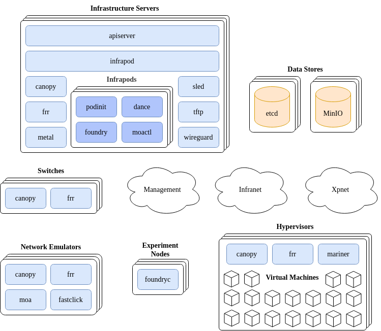
In the discussion that follows we’ll first provide a basic overview of what the components are and how they interact with each other. Then a more detailed discussion of how these components are deployed and actually communicate will follow.
When an experiment materialization is requested from a Merge portal, the request is received by the Mars API server service. The job of the API server is to take that request and turn it into a target operating state for the set of components involved in materialization of the experiment. This includes but is not limited to switch state to create virtual networks, node imaging system state to make sure that the nodes come up with the desired OS, node configuration state so that when the OS boots, user accounts are created with SSH keys and the networking stack on the node is configured according to the experiment model, network emulation state and more. It’s important to note that the API server does not call out to any of the various subsystems on the testbed directly to accomplish this desired state, it simply writes the desired state primarily to the testbed etcd data store and information that may be too large to be efficiently handled by etcd is placed in MinIO.
All of the remaining services in the testbed watch for changes of interest in the data stores. Take Canopy as an example. Canopy is responsible for synthesizing the virtual networks that interconnect experiment nodes within a materialization. Canopy runs in multiple places; on switches, infrastructure servers, network emulators, and on hypervisors. When Canopy starts up, it checks what the name of the host it’s running on is, and watches for virtual network state corresponding to that hostname in the etcd data store. When an update is detected for the node that the Canopy instance is running on, whether it be adding new virtual networking elements such as VRFs or VXLAN VTEPs, or removing those elements, Canopy will drive the underlying networking state of the platform it is running on to the current target specification.
The vast majority of the services in the Mars testbed platform operate in this way. This design pattern is known as the reconciler architecture. In this architecture the goal is to create a set of autonomous subsystems that drive underlying state toward a target goal independently and do not require a centralized orchestrator, just an observable and highly-available data store that supports change notification.
The Mars platform, and MergeTB in general is a model-driven architecture. This means that every testbed facility has an associated model that contains the details of what types of resources are contained within and how they are interconnected. The reconciler services within a testbed facility use this model in conjunction with a Merge materialization specification. A simple example of a testbed model is available in the Phobos virtual testing facility repository.
The only network in a Mars facility that is static and is required to exist prior to installation is the management network. This network interconnects the management ports of servers and switches for basic testbed ops communications. The other two types of network, infranets and xpnets are instantiated on demand by Canopy in response to materialization requests.
Core Mars Services
apiserver
As described in the section above the API server transforms materialization requests from a Merge
portal in to target state definitions in the etcd and MinIO data stores. It does this by
implementing the MergeTB Facility
API.
The primary 2 methods of this API are Materialize and Dematerialize. This content of these
requests is used to create target state definitions that make their way into etcd and MinIO.
Materialization requests contain a materialization specification that completely describes how an experiment is to be materialized, this includes
- Realization, experiment and project ids
- Materialization parameters that describe how to materialize the infranet
- Bare metal and virtual machine specifications
- Link specifications
- Physical object specifications for simulation
- Contact information for the calling Merge portal
The top level handlers that implement Materialize, Dematerialize and all of
the other Facility API endpoints in Mars are located
here.
infrapod
The infrapod service is responsible for observing changes in target state for infrapods and, reacting to those target state changes by creating or destroying infrapods. Infrapods are created per-materialization and each infrapod holds state for and interacts with a single materialization.
Infrapods are implemented as Podman pods. The infrapod service uses the Podman API to create and destroy pods, the containers within them and define how pods attach to the network. At the time of writing the Podman API does not provide much latitude in terms of how CNI specifications are defined. Therefore along side Podman we also run a service called Cniman that allows us to setup arbitrary CNI specs for Podman pods to consume and attach to the network in the exact way needed.
The code that implements the infrapod service is in service/infrapod.
At the time of writing (Mars v1.0.3), infrapods contain four containers
- dance
- foundry
- moactl
- podinit
dance
Dance is a name and address server that provides DHCP and DNS services backed by an etcd data store. On startup Dance loads its complete configuration into memory from etcd and then keeps that in-memory data in sync with etcd through watch events. All requests are served from data in memory making Dance a) eventually consistent and b) fast.
A separate Dance service runs in each infrapod. Dance is implemented at service/dance.
foundry
The Foundry container provides node configuration services for resources in an experiment.
The system images that the testbed stamps onto resources at materialization time contain a daemon
that runs at boot time. This is the Foundry client (foundryc). When the Foundry client starts, it
reaches out to the Foundry server (foundryd) at the DNS name foundry which is resolved by dance.
The Foundry server listens on an experiment materialization’s VRF and is thus only reachable by nodes in that experiment. Foundry servers are dedicated to a particular experiment and are instantiated within infrapods on a per-materialization basis. Foundry server information is populated by the infrapod reconciler at the time the infrapod is stood up.
A separate foundry service runs in each infrapod. Foundry is implemented at tech/foundry.
moactl
TODO: @bkocolos
podinit
The Podinit container implements initial bootstrapping configurations for the infrapod. At the time
of writing these are primarily (1) populating the Foundry configuration by sending machine
configurations to the Foundry API server, and (2) establishing routing and network address
translation (NAT) entries within the infrapod’s network namespace. While these options could be done
from the infrapod service itself, having them performed from a container within the infrapod
ensures that they run on each start of the pod, which makes the pod resilient to operations such as
pod restarts by a human operator.
A separate podinit service runs in each infrapod. Podinit is implemented at service/podinit.
canopy
The Canopy reconciler service is responsible for observing changes in target state for virtual networks and reacting to those target state changes by creating or removing kernel network state. Canopy runs on any testbed resource involved with managing virtual network state, which includes switches, infrastructure servers, network emulators and hypervisors.
Canopy supports a wide range of network configuration including
- VLAN access and trunk ports
- VLAN subinterfaces
- VLAN-aware bridging
- VXLAN VTEPs
- BGP Router specifications
- Physical port state
The target state key space that Canopy watches is always prefixed by the hostname of the machine the target state must be configured on. When the Canopy reconciler starts up, it determines the name of the host it’s running on and uses this to prune the state space it watches.
There are two underlying mechanisms that Canopy employs to drive underlying network state. The first is the Linux netlink subsystem. Netlink is a socket based mechanism provided by the kernel to both observe and update the kernel networking state. There is a library developed by the MergeTB team called rtnl that is used extensively by Canopy to create the desired routing, bridging and forwarding state on Linux based devices. It’s worth noting here that Cumulus Linux, DENT and Switch Linux all use the netlink subsystem to synchronize kernel network state to the underlying switch ASIC - so this approach works as expected on all of these switching and routing platforms in addition to just normal server machines running Linux.
Canopy is implemented at service/canopy.
frr
The second underlying mechanism Canopy uses to drive network state is FRR. At the time of writing we
simply subcommand calls out to the vtysh program. This is a deeply unsatisfying approach in a
number of ways, but it is the best we have at the time of writing. There is a new gRPC-based
northbound interface being implemented in FRR, but it’s not ready yet. And there is a Yang
implementation for FRR, but I think the ultimate end state for this systems interaction is going to
be through the northbound gRPC interface so I decided not to mess with Yang and just wait for
northbound to become ready.
Canopy and FRR run in different containers. Communication via Vtysh is made possible by a common mount of the FRR runtime directory into both containers. This way Unix socket communication is readily accomplished from both containers to the FRR daemons running exclusively in the FRR container.
metal
The metal service is responsible for managing the power state of bare metal assets. It works based on a plugin model that allows it to control power for any resource it has a plugin for. At the time of writing power control plugins for the following are implemented
- APC PDUs
- IPMI
- National Control Devices (NCD) Fusion Relay Board Controllers
- Raven virtual power control interface
The metal service knows what power control mechanism to use based on the testbed model. Any time the metal service handles a request, it looks up the device it is being asked to manage power for, checks the model of that device for it’s power control configuration and then uses the configured power control endpoint.
Metal is implemented at service/metal.
sled
Sled is the testbed imaging system. The sled service is responsible for observing changes in target state for node images and reacting to those target state changes by adding and removing image entries in the Sled data store.
Sled is divided into two parts a client and a server. The way the imaging process unfolds between the two is depicted in the diagram below.
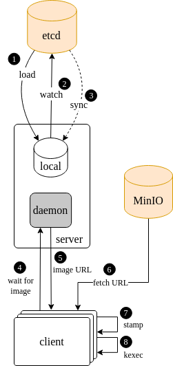
When the Sled reconciler service first starts up, it checks and caches the target image state in the Mars etcd data store. It then enters a wait loop to pick up any changes that happen over the course of it’s lifetime (yes there is an inherent race condition in the way this is colloquially described, the wait loop is actually initiated before the initial state caching so nothing is missed in between).
When a request comes in from a client for an image, the sled service either has an image config for the client or it does not. In the event that it does not, it tells the client to stand by and keeps a connection open. When a target image state does come in for this client, the image location URL will be delivered back to the client. Alternatively if the target image configuration is available at the time of call, it’s sent to the client immediately. When the client receives an image URL, it fetches the content of that URL from MinIO, all image URLs are assumed to be MinIO bucket/object URLs. Then the client stamps that image onto the disk in the image spec that was delivered to it and subsequently kexec’s into the image.
The code that implements the Sled service is in service/sled.
The Sled client is a u-root based system that is implemented here. The u-root payload is delivered to the client through a combination of DHCP/BOOTP, PXE/iPXE and a TFTP/HTTP server. These subsystems are described in the dance and tftp sections to follow.
tftp
The tftp service is responsible for serving pxe-time boot images. It is not a reconciler and
performs the very simple function of serving a static set of images that are packaged in its
container The
tftp listens on port 69 on the shared service VRF so it can be reached from any node at any time.
The almost trivial code that implements the tftp service is located at service/tftp/main.go
wireguard
TODO: @glawler
moa
TODO: @bkocolos
fastclick
TODO: @bkocolos
mariner
The Mariner container runs directly on the testbed hypervisor nodes and provides node virtualization services for experiment materializations. The Mariner reconciler observes changes in target state for virtual machines (VMs) and reacts to those changes by provisioning Qemu/KVM virtual machines.
Each materialization specification contains a (possibly empty) set of VM specifications, which denote the set of resources to be allocated that will back each VM’s virtual hardware. At the time of the Merge 1.0 release, the resource specification includes processors, memory, network interface cards (NICs), and disks that should be provisioned for a VM. The mariner container creates a new Qemu/KVM instance and initializes its virtual hardware state to map to the physical resources included in the materialization spec.
The Mariner container is responsible for wiring the infrastructure and experiment networks into each
VM it creates. For Merge 1.0, Mariner emulates all virtual NICs as either virtio, e1000 or e1000e
devices (as specified by the materialization spec.), each of which has a backend TAP device
configured as a VLAN access port that is connected to a virtual hypervisor bridge managed by the
canopy service. Mariner implementations may also support PCI passthrough device access,
which is sometimes desired for experiments requiring line-rate network performance characteristics
or that require access to physical NIC architectural features for operational reasons, but this
support is not yet provided in Merge 1.0. Currently, mariner emulates nodes using virtual CPUs
interconnected through the qemu q35 chipset.
Each VM mariner provisions is deployed in the context of a separate standalone podman container. This is done so that VM lifetimes are decoupled from the lifetime of the Mariner service itself. If and when a mariner service is restarted, it reconciles the desired hypervisor state against the set of currently provisioned VM containers, and creates or deletes the latter to converge the actual state towards the former.
The mariner system is implemented in service/mariner.
Deployment Options
Mars is a flexible system that can be deployed in a number of ways. Consider the alternatives below.
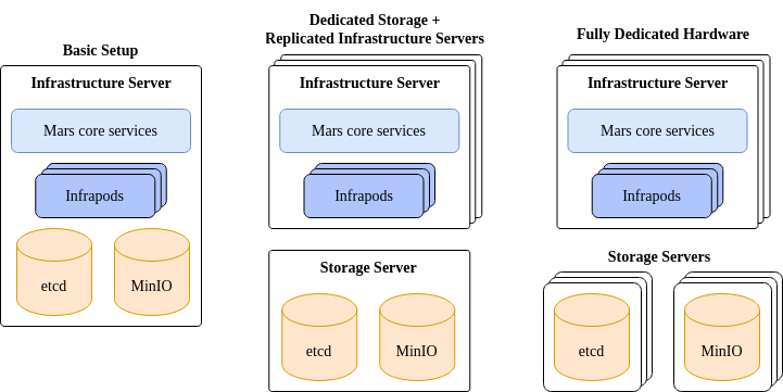
On the far left we have a single infrastructure server that hosts all the core services, infrapods and data stores. This is a simple way to get started and at the time of writing is the only tested configuration. In the middle the infrastructure servers are restricted to hosting the core services and infrapods, with dedicated storage servers used for the data stores. On the far right, the etcd and MinIO data stores each have their own dedicated set of replicated servers.
These three points in space represent possible options, not all the options. The best option for your facility depends on a number of issues such as the size of the facility, your desired availability level, and your budget.
The Mars installer is driven by the testbed model. The installer will look at the model, and based on the roles assigned to each server in the model will determine what services need to be placed on those servers. For example, for each server a Fedora CoreOS Ignition file is created that specifies exactly what needs to run on that server.
Provisioning of a Mars system is accomplished by taking the Ignition configuration files and other installation artifacts generated by the installer and feeding them to Ground Control. Ground Control is a one stop shop for provisioning Fedora CoreOS (FCOS) based systems as well as zero-touch provisioning (ZTP) enabled networking platforms such as Cumulus Linux. The installer also generates a ground-control config that can be used to provision all the infrastructure-level systems on the testbed such as infrapod servers, storage servers and switches.
See the Facility documentation for detailed information on how to model, install, deploy, and operate a Mars based facility.
Feedback
Was this page helpful?
Glad to hear it! Please tell us how we can improve.
Sorry to hear that. Please tell us how we can improve.